 | Info
Sheets |
| | | | | | | | | | | | | | | | | | | | | | | | |
 | Out-
side |
| | | | |
|
| | | | |
Result : Searchterm 'Flow Compensation' found in 1 term [ ] and 12 definitions [ ] and 12 definitions [ ], (+ 5 Boolean[ ], (+ 5 Boolean[ ] results ] results
| | previous 11 - 15 (of 18) nextResult Pages : [1] [2 3] [4] |  | |  | Searchterm 'Flow Compensation' was also found in the following service: | | | | |
| |  |
| |
|
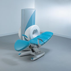
From ONI Medical Systems, Inc.;
MSK-Extreme™ MRI system is a dedicated high field extremity imaging device, designed to provide orthopedic surgeons and other physicians with detailed diagnostic images of the foot, ankle, knee, hand, wrist and elbow, all with the clinical confidence and advantages derived from high field, whole body MRI units. The light weight (less than 650 kg) of the OrthOne System performs rapid patient studies, is easy to operate, has a patient friendly open environment and can be installed in a practice office or hospital, all at a cost similar to a low field extremity machine.
New features include a more powerful operating system that offers increased scan speed as well as a 160-mm knee coil with higher signal to noise ratio, and the option of a CD burner.
Device Information and Specification 16 cm knee, 18 cm lower extremity;; 12.3 cm upper extremity, additional high resolution v-SPEC Coils: 80 mm, 100 mm, or 145 mm. SE, FSE, GE2D, GE3D, Inversion recovery (IR), Driven Equilibrium, Fat Saturation (FS), STIR, MT, PD, Flow Compensation (FC), RF spoiling, MTE, No Phase Wrap (NPW) IMAGING MODES Scout, single, multislice, volume 2D less than 200 msec/image X/Y: 64-512; 2 pixel steps 4,096 grey lvls; 256 lvls in 3D POWER REQUIREMENTS 115VAC, 1phase, 20A; 208VAC, 3 phase, 30A COOLING SYSTEM TYPE LHe with 2 stage cold head 1.25m radial x 1.8m axial | | | | | |  Further Reading: Further Reading: | Basics:
|
|
| |
| | | | | |
| |
|
Quick Overview
Please note that there are different common names for this artifact.
NAME
Motion, phase encoded motion, instability, smearing
REASON
Movement of the imaged object
HELP
Compensation techniques, more averages, anti spasmodic
Patient motion is the largest physiological effect that causes artifacts, often resulting from involuntary movements (e.g. respiration, cardiac motion and blood flow, eye movements and swallowing) and minor subject movements.
Movement of the object being imaged during the sequence results in inconsistencies in phase and amplitude, which lead to blurring and ghosting. The nature of the artifact depends on the timing of the motion with respect to the acquisition. Causes of motion artifacts can also be mechanical vibrations, cryogen boiling, large iron objects moving in the fringe field (e.g. an elevator), loose connections anywhere, pulse timing variations, as well as sample motion. These artifacts appear in the phase encoding direction, independent of the direction of the motion.

Image Guidance
| | | |
• View the DATABASE results for 'Motion Artifact' (24).
| | | | | | Further Reading: | | Basics:
|
|
News & More:
| |
| |
| | | | | |
| |
|
| | | |
• View the DATABASE results for 'Multi Echo Data Image Combination' (2).
| | | | |
| | | Searchterm 'Flow Compensation' was also found in the following service: | | | | |
| |  |
| |
|
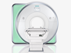
From Siemens Medical Systems;
Received FDA clearance in 2010.
The MAGNETOM Aera is a patient friendly, comfortable 1.5 Tesla MRI system with advanced radio frequency chain.
The system is equipped with the Tim 4G and Dot system (Total imaging matrix + Day optimizing throughput), to enhance both productivity and image quality.
Tim 4G technology provides improved SNR. The standard system configuration of 48 radio frequency channels and 204 coil elements creates an imaging matrix that allows maximum use of coil elements at full field of view. Dot provides improved image consistency through new features like auto align, auto FoV and automatic bolus detection.
Device Information and Specification
CLINICAL APPLICATION
Whole body
Head, spine, torso/ body coil, neurovascular, cardiac, neck, shoulder, knee, wrist, foot//ankle and multi-purpose flex coils. Peripheral vascular, breast, shoulder. Up to 60% more SNR with Tim 4G.
CHANNELS (min. / max. configuration)
48, 64
MINIMUM TE
3-D GRE: 0.22 (256 matrix), Ultra-short TE
At isocenter: L-R 70 cm, A-P (with table) 55 cm
MAGNET WEIGHT (gantry included)
3121 kg
DIMENSION H*W*D (gantry included)
145 x 231 x 219 cm
MAX. AMPLITUDE
33 or 45 mT/m
3 linear with 20 coils, 5 nonlinear 2nd-order
POWER REQUIREMENTS
380 / 400 / 420 / 440 / 460 / 480 V, 3-phase + ground; 85 kVA
| | | | | |
| | | | | |
| |
|
An image artifact is a structure not normally present but visible as a result of a limitation or malfunction in the hardware or software of the MRI device, or in other cases a consequence of environmental influences as heat or humidity or it can be caused by the human body (blood flow, implants etc.). The knowledge of MRI artifacts (brit. artefacts) and noise producing factors is important for continuing maintenance of high image quality. Artifacts may be very noticeable or just a few pixels out of balance but can give confusing artifactual appearances with pathology that may be misdiagnosed.
Changes in patient position, different pulse sequences, metallic artifacts, or other imaging variables can cause image distortions, which can be reduced by the operator; artifacts due to the MR system may require a service engineer.
Many types of artifacts may occur in magnetic resonance imaging. Artifacts in magnetic resonance imaging are typically classified as to their basic principles, e.g.:
•
Physiologic (motion, flow)
•
Hardware (electromagnetic spikes, ringing)
Several techniques are developed to reduce these artifacts (e.g. respiratory compensation, cardiac gating, eddy current compensation) but sometimes these effects can also be exploited, e.g. for flow measurements.
See also the related poll result: ' Most outages of your scanning system are caused by failure of'
| | | |
• View the DATABASE results for 'Artifact' (166).
| | | | | | Further Reading: | | Basics:
|
|
News & More:
| |
| |
| | | | |
| | | |
|
| |
 | Look
Ups |
| |


